

Correct solar array sizing starts with the site’s required daily energy, divided by effective peak sun hours and adjusted for project-specific losses. The result must then be checked against battery charge-current limits, PV input limits, seasonal conditions, and daytime loads. Commercial buyers can evaluate Sorotec hybrid inverters and MPPT controllers within this process.
What Project Inputs Determine the Required Array Capacity?
Array capacity cannot be calculated from battery capacity alone. Buyers need the facility load profile, required backup duration, battery limits, and available solar resource.
Establish the Facility’s Daily Energy Demand
Prepare a load schedule covering operating hours, continuous equipment, intermittent machinery, startup loads, and planned expansion. Use interval-meter data where possible instead of relying only on nameplate ratings. Separate energy used during solar-production hours from energy that must be stored for nighttime operation or outages.
Define Battery Capacity, Usable Energy, and Required Autonomy
Calculate nominal battery energy as:
Nominal energy (kWh) = bank voltage × amp-hour capacity ÷ 1,000
Apply the approved state-of-charge range, temperature restrictions, and discharge limits rather than treating all nominal capacity as usable. Define whether the required autonomy covers overnight loads, short outages, or several low-solar days.
Confirm the Battery’s Permitted Charging Rate
Check the recommended and maximum continuous charge current for the battery modules, complete bank, and BMS. Include solar, grid, and generator charging when these sources may operate together. The combined limit should follow the lowest applicable rating among the battery, BMS, and charging equipment. PV oversizing is acceptable only when controls keep battery-side charging within that limit.
| Project input | Why it affects array sizing | Required project record |
| Daily load energy | Sets the energy-production target | Meter data and load schedule |
| Usable battery energy | Defines stored-energy demand | Battery voltage, capacity, and usable range |
| Required autonomy | Determines reserve requirements | Approved operating strategy |
| Charge-current limit | Caps battery-side charging power | Battery and BMS settings |
How Should Buyers Convert Energy Demand Into PV Capacity?
Convert the established energy demand into an initial PV rating, then adjust it for the site’s critical operating conditions.
Calculate the Baseline Array Size
Use this planning relationship:
Baseline PV capacity (kW) = required daily solar energy (kWh) ÷ effective peak sun hours ÷ project performance factor
Required solar energy may include daytime consumption and battery recharge. Keep energy in kilowatt-hours and array power in kilowatts to avoid confusing battery capacity with instantaneous charging power.
Account for Seasonal Irradiance and Real-World Losses
Design around the lowest-solar period relevant to the facility, not just the annual average. Account for module temperature, soiling, shading, cable loss, mismatch, conversion loss, orientation, and equipment availability. Design margin should reflect operating risk, backup availability, and the cost of unmet loads.
Test the Result Against Charging Time and Operating Priorities
Model whether the array can supply concurrent daytime loads while restoring the battery within the required charging window. Compare normal operation, low-irradiance periods, and recovery after a permitted deep discharge. A larger battery does not support a larger array when PV-input or battery charge-current limits have already been reached.
Apply a Final Sizing Gate
Record the energy-based PV target, equipment PV voltage, current and power limits, and the battery bank’s permitted charging limit. Approval requires one configuration to satisfy all three checks under the critical seasonal condition. If the target exceeds an electrical or charging limit, revise the architecture, charging window, load strategy, or equipment selection rather than simply adding modules.
How Can Designers Verify PV String and MPPT Compatibility?
Energy calculations establish the required capacity. Electrical checks determine whether the proposed module strings can operate safely and effectively with the inverter or controller.
Check Voltage Across Expected Temperature Conditions
Calculate cold-weather string open-circuit voltage and keep it below the absolute PV input limit. Hot-weather operating voltage must remain within the verified MPPT window. Startup voltage is separate: a higher threshold can delay startup under weak dawn irradiance or cause earlier shutdown during weak dusk conditions.
Verify PV Current, Controller Capacity, and Battery-Side Output
Compare string current and parallel-string totals with per-input and total current limits, and check maximum PV power separately. Convert controller output to battery-side charging current and compare it with battery and BMS limits, including simultaneous AC charging.
Evaluate DC-to-AC Ratio and Potential Clipping
Clipping is determined by the relationship between available DC power and the inverter’s AC conversion capacity, not simply by high PV voltage. Production modelling should compare energy gained through moderate DC oversizing with energy curtailed during high-output periods. A high-voltage inverter does not inherently prevent clipping.
Which SOROTEC Equipment Roles Should Be Evaluated?
Selection should follow the project calculations. Each option requires verification against the battery, strings, phase arrangement, and installation environment.
| Equipment | Confirmed role and features | Main buyer checks |
| REVO VM II PRO | Hybrid inverter; 1.6–10kW models; 60–450VDC PV range | MPPT limits, battery voltage, phase, IP rating, BMS protocol |
| MPPT SSC Series | Dedicated 40A, 60A, 80A, or 100A charging | PV limits, programmable charge values, derating |
| REVO HMT IP54 L3P G2 | Three-phase hybrid inverter; 6–12kW; IP54 | Battery compatibility, configuration, system architecture |
Assess REVO VM II PRO as the Priority Hybrid Inverter Option
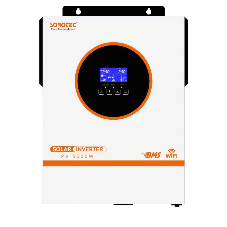
The Off Grid REVO VM IIPRO Series 1.6/3.2/4/6/8/10KW is a hybrid solar inverter for on-grid and off-grid applications. It offers a 60–450VDC PV range, battery-free operation, a reserved CAN or RS485 BMS communication port, built-in Wi-Fi, and an anti-dust kit.
Treat 60–450VDC as the specified PV range, not a confirmed MPPT window or maximum open-circuit voltage. Verify PV power, MPPT limits, battery voltage, LiFePO4 settings, phase, IP rating, and protocol compatibility. Parallel operation is model-dependent.
Consider a Dedicated MPPT Charging Architecture
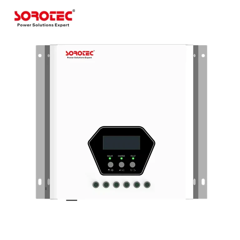
The MPPT SSC Series 40A/60A/80A/100A can provide a separate solar-charging stage. It includes MPPT tracking, automatic battery-voltage detection, three-stage charging, automatic load detection, an LCD, and listed reverse-polarity protection.
Three-stage charging does not by itself establish LiFePO4 compatibility. Confirm programmable voltage values, charging logic, supported battery voltages, PV limits, temperature behavior, and output-current derating.
Review the Confirmed Three-Phase Alternative Carefully
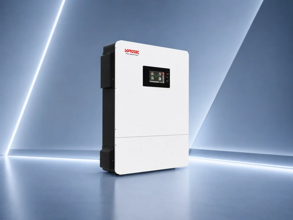
The Three-Phase IP54 REVO HMT IP54 L3P G2 Hybrid Energy Storage Inverter 6-12kW is a three-phase hybrid option with a 6–12kW range and IP54 designation. Configuration can be customized, but battery and PV suitability requires written technical confirmation. Larger projects may need multiple units or another verified architecture.
What Should Be Validated Before Procurement and Commissioning?
Convert calculations and compatibility assumptions into a controlled project schedule before ordering equipment.
Complete a Product-to-Project Compatibility Matrix
Record string operating voltage, cold open-circuit voltage, PV current, PV power, battery voltage, charge current, BMS protocol, environmental rating, AC output, and phase arrangement. Flag unresolved values for technical confirmation instead of using assumptions.
Model Normal, Seasonal, and Fault-Recovery Scenarios
Test typical operation, the lowest-solar design period, high module temperature, cold-weather string voltage, and recovery from a deeply discharged but BMS-permitted state. Include daytime loads and approved grid or generator support.
Finalize Protection, Monitoring, and Commissioning Requirements
Cover DC isolation, overcurrent and surge protection, grounding, cable sizing, and battery protection. During commissioning, verify charge settings, communications, alarms, remote monitoring, string voltage, charging current, operating temperature, and battery response.
Commercial buyers and EPC teams can request a project-specific technical review with their load profile, irradiance data, module specifications, battery and BMS information, phase requirements, and environmental conditions.
FAQ
Can a Solar Array Be Larger Than the LiFePO4 Battery’s Charging Requirement?
Yes, provided daytime loads can use the additional power and the inverter or controller remains within its PV voltage, current, and power limits. Battery-side charging must remain below the permitted battery and BMS charge current.
How Do Peak Sun Hours Affect the Required PV Capacity?
Fewer effective peak sun hours require more PV capacity to produce the same daily energy. Solar array sizing should use the critical seasonal resource and project-specific losses rather than only an annual-average figure.
What Happens if the PV String Does Not Match the MPPT Voltage Window?
A string below the MPPT window may not track or produce as intended, particularly in hot conditions. Excessive string voltage can exceed equipment limits during cold weather. Recalculate the module count per string before procurement.