

Hybrid solar and battery systems are often paired with diesel generators at remote facilities, telecom sites, workshops, and businesses that cannot tolerate long outages. The generator is not simply another AC source: its voltage, frequency, neutral arrangement, ramp rate, and control signals must coexist with the inverter’s battery and grid logic. A safe integration plan defines who regulates power, when the generator starts, how battery charging is limited, and how the system returns to solar-first operation.
Key Takeaways
- Treat the generator, inverter, battery, and loads as one coordinated control system.
- Confirm AC voltage, phase, frequency, neutral, grounding, and protection before connection.
- Set generator start and stop thresholds with battery reserve and load demand in mind.
- Limit generator charging current to the generator’s real capacity and operating condition.
- Witness abnormal states: failed start, overload, low fuel, communication loss, and grid return.
1. Define the Operating Priority
Write the energy priority in plain language before selecting terminals or control relays. A typical sequence may use PV for active loads, surplus PV for battery charging, battery energy during short interruptions, and generator support when reserve or load thresholds are reached. The exact sequence depends on the site and must be confirmed for the chosen inverter.
Decide whether the generator is a backup source, a scheduled peak-support source, or a regular charging source. These roles change the battery reserve, start threshold, and maintenance pattern. Avoid a design in which the generator starts for every short cloud event; excessive cycling can increase fuel use and service requirements.
2. Match the AC Interface
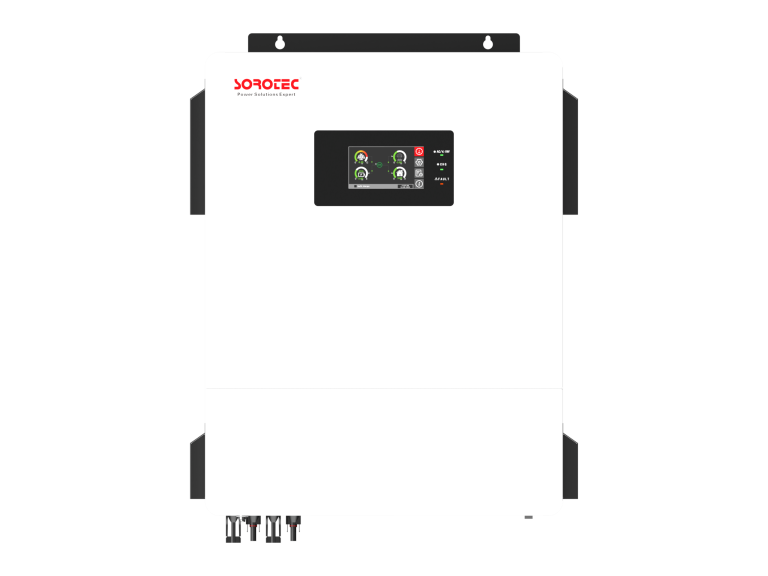
Verify generator output voltage, phase arrangement, frequency range, neutral bonding, breaker rating, and available short-circuit current against the inverter AC input. Split-phase projects may require balanced 120/240 Vac behavior; an 8, 10, or 12 kW split-phase inverter family such as SOROTEC Split-Phase IP54 REVO HMT IP54 L2P G2 Hybrid Energy Storage Inverter should be considered only when its exact model and site wiring match.
Check whether the inverter expects a separately derived neutral, whether the generator neutral is bonded, and where the transfer equipment switches the neutral. A duplicated bond can create circulating current or nuisance protection trips. The electrical engineer should approve the single-line diagram before field wiring.
Confirm the generator voltage regulator and governor performance across the planned load range. An inverter may reject a source that drifts outside its accepted voltage or frequency window, even though conventional loads continue to run. Ask both suppliers for the relevant operating windows and resolve any mismatch before procurement.
3. Coordinate Generator and Battery Charging
Generator charging is constrained by the generator’s available capacity, the inverter AC charging limit, and the simultaneous site load. Calculate the worst case rather than using the generator nameplate alone. If the generator is lightly loaded, the inverter may need a minimum loading strategy or a controlled charging profile; confirm the behavior with the equipment supplier.
For lithium batteries, closed-loop BMS information can provide charge limits and alarms when RS485 or CAN communication is supported. If communication is not available, use conservative voltage and current settings and test temperature and low-state-of-charge protections. Record how the inverter responds when the BMS removes charge permission.
Include auxiliary loads such as cooling fans, pumps, controls, and fuel systems in the generator capacity calculation. Apply the generator supplier’s derating for altitude and ambient temperature. The charging setpoint should leave a deliberate margin for step loads rather than consuming every available kilowatt during stable operation.
4. Design Start Stop and Interlocks
Use a documented two-way control path. The inverter or energy controller may request generator start, while the generator controller reports running status, warm-up completion, fault, and cooldown. A dry contact alone does not prove that the generator is ready to accept load. Include a start-failure timeout, emergency stop, manual mode, and a clear rule for who has control during maintenance.
Set start conditions using battery reserve, load demand, and outage duration. Set stop conditions with a minimum run time and cooldown so the generator does not start and stop repeatedly. Test a failed-start condition and verify that critical loads retain a safe supply or receive an alarm.
Define what happens after several failed start attempts. Repeated cranking can drain the starter battery and hide a fuel or mechanical fault. The controller should stop trying after the approved count, issue a remote alarm, and preserve the energy-storage reserve for the most important loads.
5. Manage Transients and Sensitive Loads
Generators can change voltage and frequency when large motors or compressors start. The inverter must tolerate the specified input window or isolate the load while the generator stabilizes. Review ramp rates, transfer delays, and overload behavior with the generator supplier and inverter manufacturer. Do not infer waveform quality from battery voltage; ripple and AC quality depend on conversion and filtering behavior.
Separate sensitive electronics from large starting loads where practical. Use the inverter’s load-priority or secondary-output functions only after confirming the exact model’s switching logic and current limits. Record the order in which circuits are connected during a generator event.
Where the inverter can supplement generator output from the battery, document the power limit and direction of energy flow. Confirm that the control scheme prevents unintended backfeed into a generator that is not designed to absorb power. Protection and interlocking should be demonstrated during acceptance, not inferred from menu labels.
6. Commission the Combined System
Commission solar-only, battery-only, generator-only, and combined modes. Then test generator start on low battery, generator support during a step load, charging-limit response, generator fault, communication loss, emergency stop, and return to solar-first operation. Measure AC voltage, frequency, battery current, state of charge, and alarm status at each stage.
A complete handover includes the approved schematic, relay logic, generator settings, inverter settings, BMS record, measured values, maintenance responsibilities, and fuel or runtime assumptions. SOROTEC can be asked to confirm model-specific operating limits before procurement.
Repeat a full automatic sequence after all settings have been backed up and the controls returned from manual mode. Verify remote alarms and timestamp alignment between the inverter, generator controller, and monitoring platform. Consistent timestamps make it much easier to reconstruct a fault after the commissioning team has left the site.
Run the combined system long enough to reach stable temperature and charging conditions. A brief transfer test may miss frequency hunting, repeated source rejection, overheating terminals, or a charging setpoint that slowly overloads the generator. Record generator loading and fuel assumptions with the battery charge rate and live building load.
Assign maintenance ownership across the inverter, battery, generator, transfer equipment, and communications network. Generator exercise schedules should consider battery state and site demand so a routine test does not create an avoidable outage. Keep emergency manual instructions at the equipment and ensure they cannot bypass required interlocks.
Project Checklist
| Checkpoint | Verify on site or in documents | Reason |
| AC compatibility | Voltage, phase, frequency, neutral, grounding | Avoids incompatible or unsafe connections. |
| Capacity margin | Generator output minus live load and charging | Prevents overload and unstable operation. |
| Control logic | Start, warm-up, run, fault, cooldown, stop | Coordinates two controllers safely. |
| Battery limits | BMS permission, current, temperature, reserve | Protects storage during generator charging. |
| Witness tests | Low battery, step load, failed start, recovery | Validates real operating behavior. |
Frequently Asked Questions
Can any generator connect to a hybrid inverter?
No. Voltage, phase, frequency, neutral, grounding, breaker capacity, and control behavior must all be compatible. Obtain written confirmation for the exact inverter and generator models.
Should the generator charge the battery at maximum current?
Not automatically. Charging current must leave capacity for live loads and remain within both the inverter AC charging limit and the generator’s stable operating range.
What is the most important field test?
Test a complete low-battery start sequence while a representative critical load is operating, then test generator fault and recovery. This reveals control and wiring problems that a no-load run will miss.
Conclusion
Generator integration succeeds when the operating sequence is engineered before the cables are landed. Match the AC interface, coordinate start and stop logic, respect battery and generator limits, and witness failure states under controlled conditions. SOROTEC can help installers and system integrators confirm the model-specific communication, charging, and backup parameters needed for a reliable hybrid power system.
For specifications, application support, and project coordination, visit SOROTEC official website, review the About Us page, browse case studies, or contact the team through the contact page.