

A split-phase backup design is not primarily an inverter-size question. This is a matter of circuit design: Identify all loads that need to be running during a power outage and be distributed between the 120 V and 240 V loads on L1 and L2. Identify starting surge durations for each device and calculate the amount of battery power and total amount of energy required to support desired runtime. Only after these issues have been addressed, can one compare the various inverter ratings, the limits of the PV array, the transfer characteristics and communications.
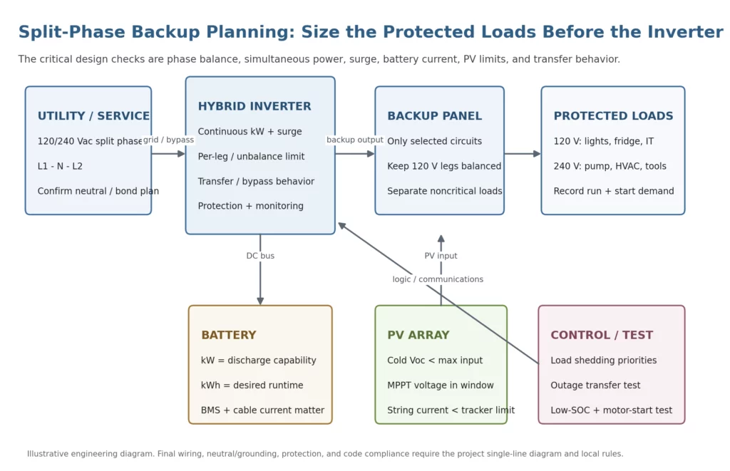
1. Start With a Protected-Load Schedule, Not the Main Service Rating
The main service rating tells you how much the building can draw under utility supply; it does not tell you what the backup inverter must carry. An installer should instead identify the circuits that are genuinely required during an outage. For each circuit, record whether it is 120 V or 240 V, which leg it uses, expected running watts, starting or inrush demand, typical duty cycle, and its priority if the system needs to shed load.
This avoids two common sizing errors. The first is oversizing from the sum of every nameplate in the house even though many loads never run together. The second is undersizing from an average-energy estimate that ignores a short pump, compressor, or tool startup. The design target is the worst credible simultaneous condition, not the theoretical sum and not the daily average.
| Example protected load | Connection | Run demand | Short peak | Outage priority |
| Refrigerator + freezer | 120 V / L1 | 0.35 kW | 1.4 kW | High |
| Lighting, router, controls | 120 V / L2 | 0.55 kW | 0.65 kW | High |
| Home office / receptacles | 120 V / L1 | 0.70 kW | 1.0 kW | Medium |
| Well pump | 240 V | 1.5 kW | 4.0 kW | High |
| Variable-speed HVAC | 240 V | 3.8 kW | 6.0 kW | Conditional |
| EV charging / electric dryer | 240 V | Excluded | — | Shed |
2. Balance the Two 120 V Legs Before Adding More Inverter Capacity
In a North American 120/240 V split-phase system, L1-to-neutral and L2-to-neutral supply 120 V loads, while a 240 V load is connected line-to-line and uses both legs. That means a 240 V pump or air conditioner contributes current to both legs, whereas a bank of 120 V receptacles may load only one side. The neutral carries the imbalance created by the 120 V line-to-neutral loads, subject to the actual waveform and harmonic content.
For backup planning, calculate current on each leg as well as total watts. If the protected panel places most kitchen, office, or lighting circuits on L1, a nominal 10 or 12 kW inverter can still be constrained by its per-leg or unbalanced-load limit. The practical fix may be circuit redistribution, not a larger inverter. Ask the inverter supplier for the permitted L1/L2 imbalance and any per-leg current limit; a total output rating alone is not enough.
3. Separate Continuous Output, Step Load, and Motor Starting Surge
Continuous power answers the question “What can the inverter carry steadily?” Surge capability answers a different question: “What happens for the first cycles or seconds after a motor, compressor, transformer, or large power supply is energized?” An inverter with enough continuous watts can still trip if the load step is too fast or the surge lasts longer than the inverter’s overload curve allows.
Record both the magnitude and duration of the difficult event. A published “2× surge” statement is not sufficient unless the duration, battery voltage, temperature, state of charge, and other conditions are defined. Where two large devices could start together, use interlocks or load-shedding logic so the design does not depend on an unlikely but expensive coincidence.
4. Check 48 V Battery Current and Runtime as Separate Design Problems
Low-voltage battery systems can require very high DC current at larger inverter power. At 12 kW, an ideal 48 V calculation is about 250 A before conversion losses. At roughly 90% DC-to-AC efficiency, the battery-side current is closer to 278 A. That current must be supported by the battery modules, BMS, busbars, disconnects, fuses, and conductor system without exceeding their continuous or transient limits.
Runtime is an energy calculation, not a power calculation. If the protected loads average 4.5 kW for four hours, they require 18 kWh of AC energy. After inverter losses and an operating reserve, the battery nameplate may need to be materially higher. The exact result depends on permitted depth of discharge, temperature, battery aging allowance, and whether PV is expected to contribute during the outage.
5. Match the PV Array to the MPPT Electrical Window
The PV check has three independent parts: voltage, current, and power. First, the cold-weather open-circuit string voltage must stay below the inverter’s maximum PV input voltage. Second, the operating string voltage must remain inside the MPPT window through the expected temperature range. Third, current from each string or parallel group must stay within the tracker input limit.
Dual MPPT does not automatically mean “two roof faces are fine.” It means the designer can allocate electrically compatible strings to independent trackers. Module Isc, Imp, temperature coefficients, parallel string count, cable losses, and array orientation still have to be checked. A string that sits below the MPPT window on hot afternoons or exceeds the current limit in strong irradiance will not be rescued by a larger inverter power rating.
6. Product Fit: SOROTEC REVO HMT IP54 L2P G2 12 kW
For projects whose protected-load analysis points to the upper end of residential split-phase backup capacity, a relevant model to evaluate is the SOROTEC REVO HMT IP54 L2P G2 12 kW split-phase hybrid energy storage inverter. The manufacturer currently publishes the family in 8 kW, 10 kW, and 12 kW versions with native 120/240 Vac split-phase output and IP54 protection. The 12 kW variant is especially useful as a screening example because its published power class is large enough to expose the battery-current, load-balance, and surge questions that installers often miss.
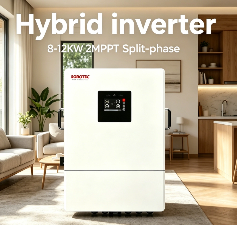
Published design-screening data for the 12 kW variant include 12,000 VA / 12,000 W rated output, 24,000 VA published surge, 120/240 Vac split-phase output, a 48 VDC battery platform, 500 VDC maximum PV open-circuit voltage, a 60–450 VDC MPPT range, two MPPT trackers with 22 A + 22 A input, up to 200 A solar charging current, IP54 protection, and published transfer times of 10 ms for PCs or 20 ms for home appliances. Use these values to screen the design, then verify the exact datasheet revision and operating conditions supplied with the quotation.
7. Worked Example: Why Total kW Alone Can Mislead
Assume the protected panel is expected to carry 1.9 kW of 120 V loads on L1, 1.6 kW of 120 V loads on L2, and 5.4 kW of 240 V loads. The total continuous demand is 8.9 kW, but the leg currents are not identical. The 240 V portion contributes about 22.5 A to both legs; the 120 V portions add about 15.8 A to L1 and 13.3 A to L2. The resulting leg currents are therefore about 38.3 A and 35.8 A before any short startup event.
Now assume a pump or compressor adds a temporary 3 kW step while the other loads remain on. The project can momentarily approach 12 kW even though the normal continuous condition is below 9 kW. An 8 kW unit may therefore be unsuitable without aggressive load shedding; a 10 kW unit may still depend on the exact surge curve; and the 12 kW variant becomes a logical candidate for detailed verification. The selection is still not final until per-leg limits, overload duration, battery current, state-of-charge behavior, and temperature derating are checked.
8. Treat Neutral, Grounding, Transfer, and Generator Interfaces as Design Items
Backup systems change source conditions when the grid disappears. The installer must know whether the inverter creates a separately derived source, whether the neutral is switched, where neutral-to-ground bonding occurs in each operating mode, and how transfer or bypass equipment prevents unintended parallel paths. A duplicated bond can cause nuisance trips or objectionable neutral current; a missing bond can create a different safety problem. These decisions belong on the single-line diagram, not in an installation-day assumption.
If a generator is included, verify its voltage and frequency window, neutral bonding, charge-current limit, and the inverter’s generator-input behavior. Charging the battery while serving backup loads can exceed a generator that appeared adequate when only its nameplate kW was compared with the inverter.
9. Commission the Failure Modes, Not Only the Normal Mode
A useful commissioning test deliberately exercises the conditions that drove the design. Verify grid loss under representative load, transfer to backup, return to grid, L1/L2 imbalance, the largest motor start, low-battery state of charge, PV recovery after sunrise, communication loss, and any load-shedding sequence. Record actual leg currents, battery current, voltage, alarms, transfer behavior, and recovery time.
Acceptance should also prove that excluded circuits stay excluded. An EV charger, electric water heater, resistance range, or dryer that was intentionally left outside the backup plan should not become an accidental outage load because of a panel or transfer-wiring mistake.
10. What to Put in the RFQ and Handover File
- Single-line diagram showing utility, inverter, battery, PV, backup panel, neutral/grounding, disconnects, and any generator.
- Protected-load schedule with 120/240 V connection, L1/L2 assignment, running watts, starting demand, priority, and load-shedding rule.
- Exact inverter model and revision, current datasheet, installation manual, certificates/listings required for the project, and firmware version where relevant.
- Battery model, usable energy, continuous and peak discharge current, BMS protocol, cable/busbar sizing, fuse/disconnect ratings, and minimum state-of-charge policy.
- PV string calculation showing cold Voc, hot Vmp, current per MPPT, conductor sizing, and shutdown/protection requirements.
- Commissioning record with measured leg current, transfer tests, motor-start test, alarm/recovery checks, settings backup, and owner training.
Conclusion
A defensible split-phase backup design begins with the loads that must survive the outage. Map those circuits to L1, L2, and 240 V; identify the worst credible simultaneous condition; then verify inverter continuous output, per-leg limits, surge behavior, battery current, battery runtime, PV input limits, transfer behavior, and neutral/grounding design. This sequence produces a system that is easier to commission and much less dependent on catalogue assumptions.
For a current product reference, review the SOROTEC REVO HMT IP54 L2P G2 8–12 kW product page and the broader SOROTEC products catalogue. Use those pages to shortlist the hardware, then require the exact model documents and project-specific approval package before release.
FAQ
Q1: Should the inverter be sized from the utility service rating?
No. Start from the protected-load schedule and the worst credible simultaneous backup condition.
Q2: Why can a system overload one leg even when total kW is acceptable?
Because 120 V loads are connected to one leg and neutral, while 240 V loads use both legs. Uneven 120 V allocation can create a per-leg constraint before the total output limit is reached.
Q3: Is surge power the same as continuous power?
No. Surge capability is temporary and must be checked with its allowed duration and operating conditions.
Q4: Why is a 48 V battery interface important at 12 kW?
Because battery-side current can exceed 250 A at full power. The battery, BMS, busbars, cables, fuses, and disconnects must all support that current.
Q5: Is 120/240 V output enough to confirm a product for a U.S. installation?
No. Voltage compatibility is only one screen. The exact regional certifications/listings, utility rules, local code requirements, and submitted model documentation must also be verified.