

Two suppliers submit different input layouts for the same roof. Compare the string maps they return, not the larger tracker count.
Let the roof drawing decide. Mark orientation, module count, and shade on each section. Three unlike groups give a third independent channel a clear role; uniform strings need a different justification.
This guide uses that test to compare a three phase hybrid inverter, then follows the decision through string design, phase loading, and the supplier inquiry.
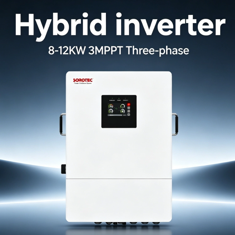
What Does an MPPT Channel Do in a Three-Phase Solar System?
Panels have a changing operating point. Their best working voltage shifts as temperature, sunlight, and shade change. The MPPT adjusts the connected PV group’s operation to follow that movement.
AC phases are a separate matter. An inverter with three trackers does not allocate one PV roof to each phase. Its DC input architecture and its AC output limits must be read independently.
Tracking the Operating Point of a PV String Group
Write a short description beside each proposed string: module, length, direction, tilt, and shade. Similar descriptions suggest strings that may share a tracker. Very different descriptions deserve a closer look before they are grouped.
Then count independent trackers, not sockets. Two string connections may feed one MPPT. The MPPT controller range illustrates why current and voltage limits must be read separately. Ask for the input diagram and current allowance for each channel; a connector count is not a substitute.
Why Independent Tracking Can Reduce Design Compromises
A roof orientation, recurring shade zone, or later build stage can form the third group. Mark it on the drawing and show why its electrical behavior differs.
There are limits to the benefit. Excess string voltage, excess current, unsuitable connectors, and poor module matching remain defects even with a spare tracker. Fix the string plan first.
When Do Three MPPT Inputs Provide a Practical Advantage?
Multiple Roof Orientations
Consider this illustrative assignment:
| PV group | Roof condition | Proposed channel |
| Main east roof | Earlier production peak | MPPT A |
| Entrance canopy | South-facing array | MPPT B |
| West extension | Later production peak | MPPT C |
The assignment makes electrical sense only after voltage and current calculations. In particular, the canopy needs enough modules to reach the working MPPT window. A roof section can be physically available yet too small for a useful string.
Uneven Shading Across the Day
Mark shadows on the roof plan at relevant hours. A parapet affecting one row in the morning is a different problem from equipment shading another row all afternoon. The tracker schedule should reflect those patterns.
Try a layout correction before assigning another channel. If shifting a row removes the obstruction, the mismatch disappears. Reserve separate tracking for differences left after sensible roof planning.
Different String Layouts or Expansion Stages
An extra input may reserve a workable path for a later roof. Put that future stage on the initial drawing with its likely module count, voltage, cable route, and protection. Otherwise “room for expansion” can mean little more than an unused connector.
When modules change between stages, review their electrical data and connectors again. Spare MPPT capacity does not make arbitrary combinations compatible.
When Are Three MPPT Inputs Unnecessary?
A uniform roof often gives a simple answer. Equal strings, identical modules, one orientation, and similar irradiance may be grouped successfully around fewer trackers, provided the current limits permit it.
Watch for a third string below the working voltage. A dedicated socket cannot cure it. The purchasing discussion may be better spent on enclosure, service, controls, efficiency, and access.
Send both suppliers the same module list and roof plan, then compare their marked connections side by side.
How Should an 8kW to 12kW Three-Phase Inverter Be Sized?
Rated kilowatts describe only part of the duty. Add motor starts, loading by phase, battery power, PV contribution, utility support, and the actual backup circuits.
Separate Continuous Load From Startup Demand
Use a phase-load schedule with these columns:
- circuit and phase;
- running power;
- startup demand and duration;
- equipment starting at the same time;
- required during an outage: yes or no.
The last column often changes the design substantially. Keeping controls, communications, and refrigeration alive may require a very different backup arrangement from carrying every machine in the building. State that scope before comparing prices.
Match PV Input to the Permitted MPPT Window
Check each channel separately. Start with cold-condition open-circuit voltage, verify normal working voltage, then check current under the planned parallel-string arrangement.
Equal shares of total PV power do not guarantee valid inputs. Some inverter channels have different current allocations. A marked manufacturer string table is more useful than an assumption that total array power can simply be divided by three.
What Should Be Checked Before Finalizing a Three-Phase Design?
Phase Conditions and Load Distribution
The brief should show supply voltage and frequency, phase sequence, neutral arrangement, and load by phase. Ask what happens on the heaviest phase during backup; total output cannot answer that.
The installer and designer must still resolve switching, isolation, export control, and local interconnection. Flexible PV inputs do not remove those AC-side obligations.
Battery, Backup, Installation, and Communication Priorities
For the battery interface, compare suitable battery storage options and record voltage, current, chemistry, and BMS protocol. On the backup side, name the circuits, transfer expectation, surges, and generator role.
For outdoor placement, inspect the enclosure in context: cooling space, derating, humidity, altitude, cable entry, and service clearance. Draw the battery, meter, and monitoring connections before ordering instead of relying on interface names alone.
How the iHESS L3P Series Fits Multi-Array Projects
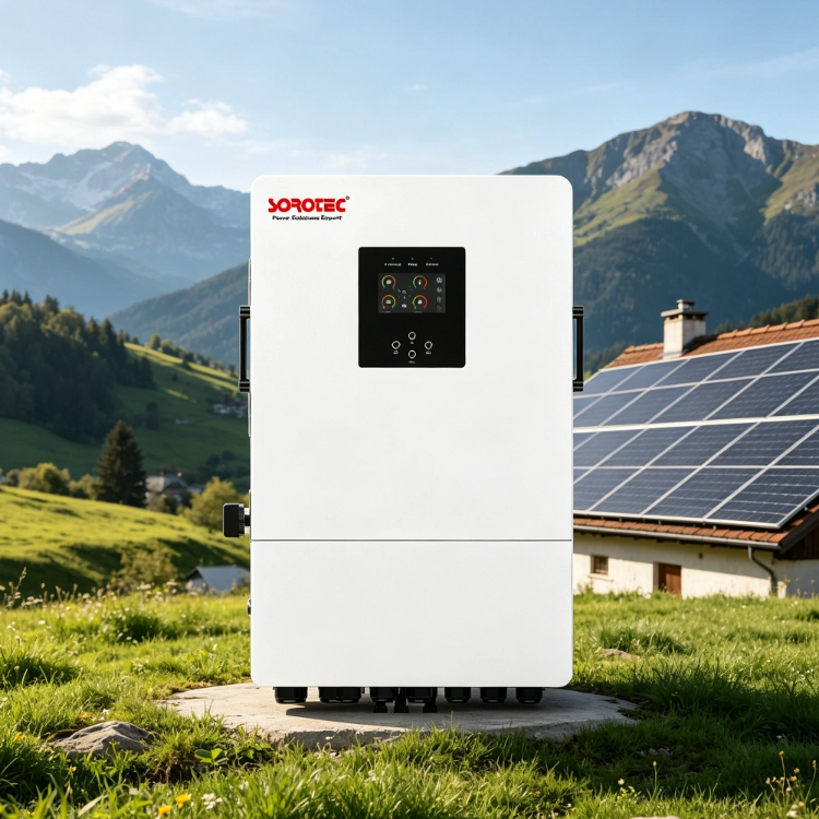
SOROTEC artwork identifies an 8–12kW iHESS L3P three-phase platform with three MPPT inputs. The supplied 2026 brochure uses the iHESS L3P G2 name for a 6–12kW family. It lists 800V maximum DC voltage, a 200–650V MPPT window, IP66 protection, 380/400/415V three-phase output, battery support, generator energy storage, and backup transfer below 10 ms.
Those two descriptions make model identification important. Before using the brochure’s compact input notation for a design, ask SOROTEC to confirm independent MPPT count, sockets per tracker, channel current limits, and the accepted string arrangement on the quoted variant.
Attach the module sheet, roof/shade drawing, proposed strings, single-line diagram, phase-load schedule, battery objective, generator details, and installation conditions. Contact the project team and ask for a marked connection proposal. That turns a general product claim into something the project designer can actually review.
FAQs
Q1: Is three MPPT always better than two MPPT?
A1: No. The additional channel needs an array group that benefits from separate tracking.
Q2: Can I connect three different roof orientations?
A2: Potentially. Each group must meet the tracker’s voltage and current requirements, and three independent channels must be confirmed on the quoted unit.
Q3: Does three MPPT mean one tracker per AC phase?
A3: No. PV tracking and AC phase output belong to different parts of the inverter.
Q4: What data should be included in a quote request?
A4: The supplier needs the roof/string drawing, module sheet, grid supply, phase-load schedule, starting events, backup circuits, battery target, and installation environment.
Conclusion
For an 8kW to 12kW three phase hybrid inverter, let the approved string map determine the tracker arrangement. Three genuinely different PV groups may justify three channels; identical strings may not. With an iHESS L3P inquiry, submit both the PV plan and phase-load schedule for review.