

Uneven loading is mainly a per-leg problem. A 120/240 V split phase inverter holds about 120 V from either live conductor to neutral and about 240 V from L1 to L2, but L1 and L2 do not have to carry the same current. Selection should therefore begin with the heavier 120 V leg. Total output, motor starting demand, neutral current, battery discharge, and transfer behavior are checked after that. The supplier also needs enough project data to confirm those conditions before shipment.
Consider a workshop with a 240 V pump, a refrigerator, lighting, receptacles, and a few computers. Its total demand may sit comfortably below the inverter’s kW rating while the receptacles and refrigeration crowd one 120 V leg. Moving a circuit can sometimes cure the problem; choosing a larger inverter will not correct a poor panel layout by itself. Protection settings, battery limits, and operating mode still have to suit the way the site is wired.
What Split Phase Output Actually Means
A split phase source uses L1, L2, neutral, and protective earth. Read either live conductor to neutral and the meter should show about 120 V. Read across L1 and L2 and it should show about 240 V because the two waveforms are 180 electrical degrees apart. A 240 V appliance is connected across both legs, whereas a 120 V appliance loads only the leg feeding its circuit.
Why Total Wattage Can Hide a Leg Overload
Take a panel carrying 3.0 kW on L1 and 1.0 kW on L2. The schedule totals 4.0 kW, but the L1 side of the inverter and its conductors are already doing most of the work. Starting a 2.0 kW, 240 V water pump adds current to both legs and does not remove the original 2.0 kW imbalance. Both figures matter: the inverter must carry the overall demand and the loading on the busier leg.
Neutral Current Under Uneven Loading
Balanced 120 V currents largely cancel in the neutral because L1 and L2 are opposite in phase. Any difference returns through neutral. With simple resistive loads, for example, 25 A on L1 and 10 A on L2 produces roughly 15 A in the neutral conductor. Electronic loads can add harmonic current, so an installer should verify the result with measurements rather than treating subtraction as the whole neutral-sizing exercise.
Four Checks That Define a Workable Inverter Size
The nameplate kW figure is only the first check. A workable split phase design must pass four linked tests before equipment enters production or is released for delivery.
| Check | Calculation or evidence | Common failure |
| Continuous output | Maximum simultaneous W or VA on L1, L2, and L1-L2 | Total load fits, but one 120 V leg does not |
| Motor surge | Starting VA and duration for pumps, compressors, and tools | Voltage dips or inverter trips at startup |
| Battery current | AC load divided by DC voltage and conversion efficiency | Battery or BMS current limit is exceeded |
| PV input | Cold-weather string Voc, operating Vmp, and input current per MPPT | Array exceeds voltage or current boundary |
Begin with a circuit list. Put every 120 V circuit on its assigned leg and mark realistic simultaneous demand rather than adding every breaker rating. Then add 240 V loads to both columns. This worksheet shows whether circuits can be rebalanced and gives the factory application team concrete data for model selection, parameter confirmation, and any OEM or ODM configuration required for the project.
Surge Is a Time Problem, Not Just a Bigger Number
A motor may draw several times its running current during acceleration. Whether the inverter carries that start depends on surge magnitude, duration, battery voltage sag, cable resistance, and the background load. Ask for the surge curve or an explicit supported duration, and provide pump or compressor data during selection. This lets the supplier check the actual duty instead of matching only a headline power rating.
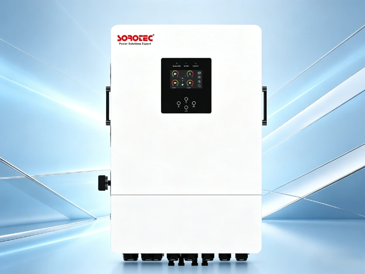
How the iHESS L2P G2 Fits Split Phase Systems
The 8, 10, and 12 kW versions of the iHESS L2P G2 split phase hybrid inverter provide 120/240 Vac split phase output from a 48 VDC battery system. Published specifications list 16, 20, and 24 kVA surge power respectively, 120/240 Vac regulation within +/-5% in battery mode, and peak efficiency of 93%. The 8 kW model lists 180 A maximum solar charging; the 10 and 12 kW models list 200 A.
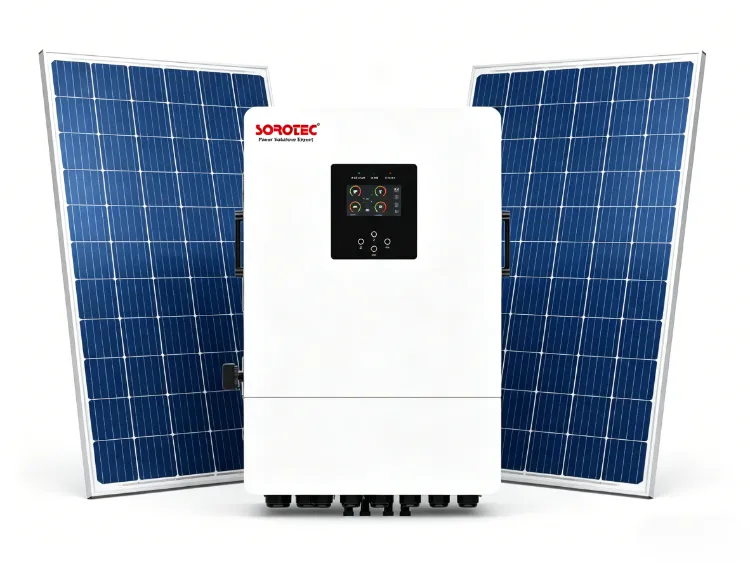
For the PV side, the published figures are two MPPT trackers, a 60-450 VDC tracking range, 22 A + 22 A maximum input current, and 500 VDC maximum array open-circuit voltage. These limits answer different questions. Correct string Voc for the coldest expected module temperature, then check how many parallel strings feed each tracker. Staying inside the voltage window does not excuse excess current, and sending the module datasheet and proposed string plan to the factory can prevent a late redesign.
Battery Current Is the Quiet Constraint
A 48 V battery system supplying 10 kW can deliver more than 200 A once operating voltage and conversion losses are considered. That current passes through more than the cells. BMS limits, busbars, fuses, disconnects, lugs, and cable resistance all affect whether the inverter can sustain its rated output. The battery model and communication protocol should be reviewed before delivery, while cable length and termination quality still need to be checked on site.
Transfer Time and Load Classification
Published transfer times are 10 ms for personal computers and 20 ms for home appliances. That can suit many loads, but equipment with sensitive contactors, poorly buffered controls, or strict ride-through requirements still needs a site test. Do not assume every device described as ‘electronic’ will react like a desktop computer.
Commissioning Uneven Loads Without Guesswork
Commissioning should recreate the operating combinations that drove the design. Measure L1, L2, neutral, battery current, and output voltage while adding loads in a controlled order, then start the largest motor with ordinary background loads present. Recording these values creates an acceptance baseline that the supplier’s after-sales team can use to diagnose later trips without relying on guesswork.
Two field mistakes recur. Installers may balance the board once, then occupants add heaters or kitchen appliances to one leg. Leave a panel schedule and measured leg currents so future changes can be checked. Commissioning is also sometimes completed with the grid present even though battery operation is the critical scenario. Repeat the heavy-load test in backup mode and retain settings, alarm records, and wiring photos for faster remote support.
A useful sizing cross-check is the site’s daily energy requirement, but energy and instantaneous power are different constraints. The guide to sizing solar power for 120 V and 240 V split phase loads can support the array and energy calculation after the leg-by-leg load schedule is complete.
When a Split Phase Inverter Is the Wrong Choice
Split phase is appropriate when the distribution system genuinely requires both 120 V line-to-neutral and 240 V line-to-line service. It is not a substitute for a three-phase source, and it should not be specified for a site whose motors or utility interconnection require three-phase power. Nor should a residential-scale unit be stretched into a 50-300 kW commercial duty simply because several units can be connected.
The installation environment can rule out an otherwise suitable model. Published iHESS L2P G2 data gives an operating range of -10 to 50 degrees C, 5-95% non-condensing relative humidity, IP66 protection, and derating at 2,000 m altitude. IP66 addresses ingress; it says nothing about trapped heat, standing water, salt exposure, or code clearance. Giving the factory the site temperature, altitude, mounting location, and corrosion conditions allows those details to be reviewed before production.
SOROTEC has worked in power electronics and new energy since 2006 and supports OEM and ODM projects. Before ordering, send a one-line diagram, the L1/L2 load schedule, motor starting information, PV module data, battery BMS protocol, ambient conditions, and grid requirements. Its application case library and technical team can then be used to check whether the selected architecture fits the actual site rather than an average load estimate.
FAQ
Can a 120 240V Split Phase Inverter Run 120V and 240V Loads at the Same Time?
Yes, if the operating combination stays within the total output rating and the limit for each 120 V leg. Battery current, motor starting demand, and conductor capacity must also remain acceptable. The 240 V appliance draws across L1 and L2; a 120 V appliance loads only the leg to which its circuit is connected.
Does Moving Circuits Between L1 and L2 Reduce Energy Use?
Usually it does not change the energy consumed by those appliances. It redistributes current, which can prevent a leg overload, reduce neutral current, and make better use of the inverter’s available output.
What Data Should Be Sent Before a Split Phase Inverter Is Selected?
Send the actual voltage and frequency, L1 and L2 running loads, motor starting data, required backup time, and the installation conditions. Include PV module Voc, Vmp, Isc, and Imp, the lowest expected temperature, plus battery voltage and BMS limits. With the one-line diagram and local interconnection rules, the factory can review the model and quotation more efficiently. The same record also gives commissioning and after-sales teams a useful starting point if the site later reports a trip.