

A hybrid solar inverter is not fully delivered when it powers up. For an EPC contractor, acceptance depends on whether the system follows the approved design during normal operation, grid failure, battery charging, and recovery. A commissioning test plan turns those expectations into witnessed steps, measured values, and signed records. It also exposes wiring, configuration, and communication faults before the site is handed to the owner.
Key Takeaways
- Define pass or fail criteria before equipment arrives on site.
- Test the complete energy path: PV, battery, grid, backup loads, and monitoring.
- Record measured values and firmware versions instead of relying on screenshots alone.
- Use controlled fault tests for transfer, low battery, BMS alarms, and overload behavior.
- Close every punch-list item with an owner, evidence, and retest date.
1. Start With the Approved System Boundary
The test plan should identify exactly what the EPC contractor is commissioning. Include the inverter model, battery model, PV array sections, AC distribution, backup panel, communications gateway, generator interface if present, and meters used for verification. Mark each boundary on a single-line diagram. This prevents a common handover problem: the inverter passes a local power-up test while the battery, protection, or monitoring system remains unverified.
List the intended operating modes: grid-connected self-consumption, battery charging from PV, battery charging from AC when allowed, backup operation, and controlled shutdown. If a grid-connected option is model-dependent, record that assumption and obtain written confirmation before testing.
2. Verify Installation Before Energizing
A visual and mechanical inspection catches more defects than a late software test. Check conductor torque, DC polarity, isolator labeling, protective devices, cable routing, ventilation clearance, enclosure condition, and the separation of communications wiring from high-current conductors. Confirm that the neutral and grounding arrangement matches the approved design and local requirements.
For a 48 V battery system, inspect fuse ratings, conductor size, lug crimp quality, and the accessible disconnect. High DC current makes loose terminations and undersized conductors a heat and voltage-drop risk. Photograph each inspection point and attach the result to the test record.
Record ambient temperature and confirm that air paths are not blocked by cable trays, walls, or stored materials. Check that service technicians can reach isolators and terminals without removing unrelated equipment. If the enclosure is installed in a dusty, humid, or semi-outdoor location, verify the delivered ingress-protection rating and cable-gland installation against the project requirement.
3. Test PV and MPPT Behavior
Measure array open-circuit voltage and polarity before closing the PV isolator. Compare the result with the inverter maximum DC voltage and the planned MPPT window. Under irradiance, record operating voltage and current for each tracker or input group. A string that looks acceptable at noon may leave the tracking window in hot weather or exceed the voltage limit during cold mornings, so the design calculation should remain part of the commissioning file.
Do not use a headline charge-current value as proof that the array is correctly matched. Confirm the number of strings per tracker, short-circuit current, PV input power, and battery charge limit together. Any deviation from the approved string schedule should trigger a design review, not an informal field adjustment.
Compare current between nominally identical strings when irradiance is stable. A material difference can indicate shading, a connector problem, reversed polarity, a damaged module, or an incorrect string count. Note the irradiance and module temperature with the reading; otherwise, later reviewers cannot distinguish an array fault from changing weather.
4. Validate Battery and BMS Sequences
Confirm battery chemistry, nominal voltage, temperature sensors, and the selected charge and discharge limits. If RS485 or CAN is used, record the cable pinout, protocol, baud rate, battery address, and firmware versions. Disconnecting communications for a controlled test should produce the expected alarm or fallback behavior; the inverter must not silently continue with unsafe limits.
Run a charge test and a discharge test at a controlled load. Verify that the battery reports state of charge, current limits, and protection alarms. Test the low-state-of-charge reserve and confirm that non-essential loads are shed before the battery reaches its configured minimum.
Where several battery modules operate in parallel, record module voltages, temperatures, and state-of-charge values before and after the test. Large differences may point to an addressing, balancing, cabling, or module-state problem. Confirm the manufacturer’s permitted difference rather than inventing a universal tolerance.
5. Witness Grid Failure and Recovery
Open the approved upstream device to simulate a grid outage, then verify that the backup output energizes the intended circuits according to the design. Measure transfer behavior, output voltage, frequency, neutral reference, and load response. Test a representative motor or inrush load only when the equipment and safety plan permit it.
Restore the grid and observe synchronization, reconnection delay, battery charging, and the return of secondary loads. The system should not reconnect simply because voltage is present; the control sequence and protection settings must be confirmed. Record every alarm and its clearance method.
Repeat the outage test at more than one battery state of charge and with different load combinations. One successful transfer at light load does not prove the system will behave correctly near its operating limit. The test leader should stop the sequence if voltage, frequency, temperature, noise, or odor indicates an unsafe condition.
6. Handover Evidence That Survives Service Calls
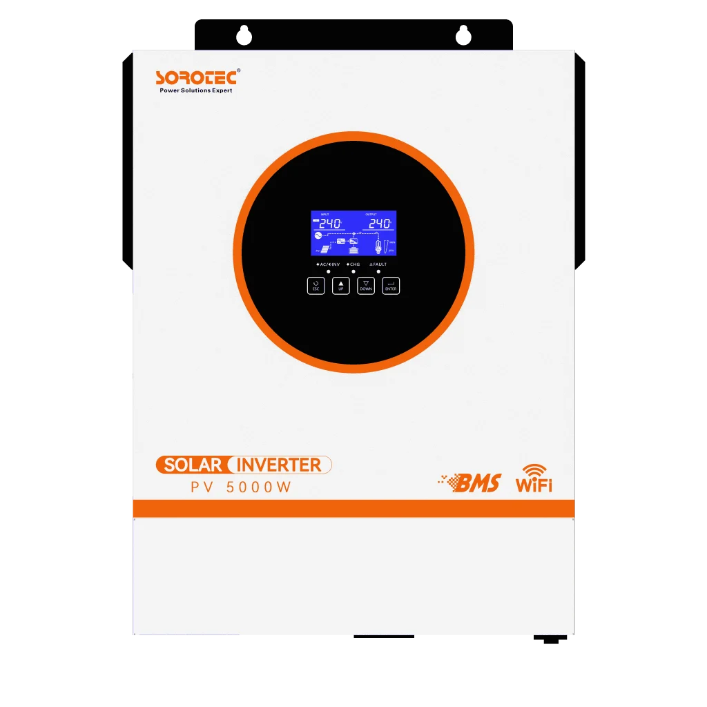
A useful handover pack includes the as-built single-line diagram, settings export, test sheets, photos, alarm history, BMS compatibility record, maintenance intervals, spare-part contacts, and a list of unresolved limitations. SOROTEC product families such as the REVO VM II PRO includes optional monitoring or battery communication features in source notes; the exact enabled functions should be recorded for the delivered model.
Keep measured values next to the acceptance limit and instrument identification. If a value cannot be verified during commissioning, state “pending confirmation” and assign a responsible party. This is more reliable than replacing a missing measurement with a generic claim that the system is ready.
Train the owner on normal status indications, isolation steps, alarm escalation, and the limits of backup operation. The training record should name the participants and equipment covered. Operators should know which circuits are supported and what action to take after a prolonged outage; otherwise, a technically sound installation can still be misused.
Before final acceptance, review the punch list by risk rather than by convenience. Safety or protection defects should block energization; functional defects should block the affected operating mode; documentation gaps should receive a dated closeout action. Retest corrected items using the same procedure and instrument class as the original test so the results can be compared.
Create a baseline trend record after the system has operated under representative load. Save daily energy flow, maximum battery current, minimum state of charge, inverter temperature, and alarm counts where the monitoring platform exposes them. That baseline gives the service team a reference when an owner later reports reduced output or unexpected battery use.
Project Checklist
| Checkpoint | Verify on site or in documents | Reason |
| AC wiring | Torque, polarity, grounding, protection, labels | Prevents unsafe energization. |
| PV inputs | Voltage, current, tracker allocation, polarity | Confirms array fit across operating conditions. |
| Battery/BMS | Chemistry, limits, RS485/CAN data, alarms | Protects the battery and inverter. |
| Backup transfer | Outage, recovery, load response, reconnection | Proves continuity for critical circuits. |
| Handover | Settings, photos, instruments, punch list | Makes acceptance traceable. |
Frequently Asked Questions
Can commissioning be completed without a battery load test?
No. A no-load startup can confirm basic wiring, but it cannot prove discharge limits, transfer behavior, low-battery protection, or load response. Schedule a controlled load test with the owner and record the result.
What if the BMS cable connects but no data appears?
Stop closed-loop operation and verify pinout, protocol, address, baud rate, termination, and firmware. Do not assume that identical connectors use identical communication assignments.
Who should approve the test plan?
The EPC lead, electrical engineer, equipment supplier, and owner representative should agree on test boundaries and pass criteria before energization.
Conclusion
A commissioning plan is a risk-control document, not paperwork added at the end of an installation. By testing the electrical architecture, DC inputs, BMS communication, transfer sequence, and evidence package as one system, an EPC contractor can hand over a hybrid inverter with fewer surprises. Ask SOROTEC to confirm model-specific limits and communication requirements before the first test day, then retain the signed results for future service work.
For specifications, application support, and project coordination, visit SOROTEC official website, review the About Us page, browse case studies, or contact the team through the contact page.