

BMS communication and MPPT limits govern two energy paths in a hybrid inverter: the battery interface and the photovoltaic input. Commissioning succeeds only when both paths stay inside their electrical and communication boundaries. A battery cable carrying current does not prove that CAN or RS485 data is valid, and a PV string inside the voltage range may still exceed the permitted input current. Product capability, factory configuration, and site verification must therefore be treated as one process.
Treating setup as a sequence of menu choices hides these distinctions. Start with the battery protocol and protection limits, verify PV voltage and current under site conditions, and only then apply meaningful load tests. Sending the protocol, firmware, module data, and string plan to the supplier before production reduces nuisance trips and prevents a commissioning problem from being mistaken for a product fault.
The Battery and PV Interfaces Solve Different Problems
A battery management system watches cell voltage, temperature, state of charge, allowable charge current, and allowable discharge current. The inverter converts energy and follows those limits. The MPPT controller, by contrast, adjusts the PV operating point to draw useful power from the array while remaining inside the inverter’s input envelope.
Closed Loop Battery Control
With a supported CAN or RS485 protocol, the battery can communicate dynamic limits instead of relying solely on fixed inverter settings. During low temperature, high cell voltage, or low state of charge, the BMS may reduce or stop current. The inverter should respond without repeatedly reconnecting. Protocol selection, pinout, termination, device address, baud rate, and firmware compatibility all matter; sharing the same connector type proves none of them.
MPPT Is an Operating Window
An MPPT voltage range describes where tracking can operate. Maximum open-circuit voltage is a separate ceiling, and input current is another boundary again. Cold weather raises module Voc, while strong irradiance and parallel strings raise available current. A string design must satisfy all three conditions instead of checking only its nominal voltage.
A Pre Power Checklist That Prevents Expensive Errors
Before the DC disconnect is closed, compare project values with the exact model manual and record them. This short check can protect the input stage and prevent a battery from silently falling back to open-loop charging. It also creates a clear handover between factory configuration, installer verification, and after-sales support.
| Interface | Verify before energizing | Evidence at commissioning |
| Battery DC | Polarity, fuse, disconnect, cable size, torque, battery voltage | Measured voltage and torque record |
| BMS link | CAN/RS485 choice, cable pinout, protocol, address, firmware | Stable SOC and current-limit data |
| PV string | Cold Voc, operating Vmp, Isc/Imp, strings per tracker | Measured polarity and open-circuit voltage |
| AC side | Voltage, frequency, neutral/earth arrangement, breaker rating | Correct phase and transfer test |
Do not use a generic Ethernet patch lead merely because the communication sockets accept RJ45 plugs. Battery manufacturers may assign CAN-H, CAN-L, ground, and wake signals to different pins. A wrong pinout can cause lost or intermittent communication. Confirm the cable definition and supported protocol with the inverter supplier before wiring, especially for OEM or multi-brand battery projects.
Confirm What the Display Is Really Showing
A plausible state-of-charge figure is not enough. Confirm that the inverter displays changing battery voltage, charge or discharge current limits, and alarm state as conditions change. If communication is lost, establish whether the inverter stops, alarms, or reverts to voltage settings. Record that agreed fallback behavior in the commissioning file so installers and after-sales engineers work from the same reference.
A Concrete 2.2 kW Commissioning Example
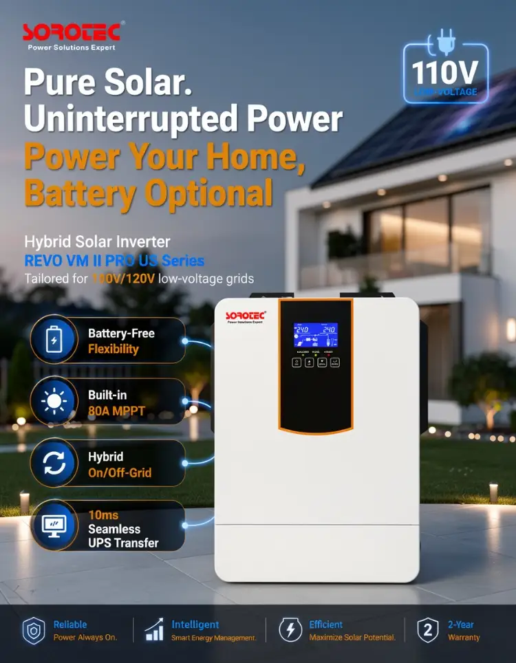
The REVO VM II PRO US 2.2 kW hybrid solar inverter is a single-phase 110/120 V unit with a built-in 80 A MPPT controller. The product information reserves RS485/CAN communication for a lithium battery BMS, supports battery equalization, offers optional grid-connected operation, and provides two outputs for smart load management. Those capabilities make it suitable for a small residential or light-duty backup design; they do not make it a large commercial inverter.
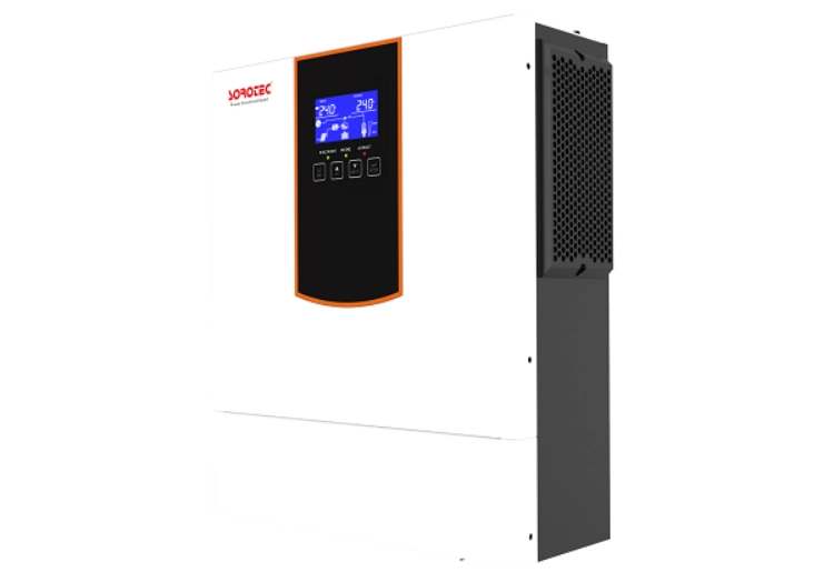
The 80 A controller rating does not permit any array capable of producing 80 A. Module strings must still comply with the exact model’s open-circuit voltage, MPPT range, and input-current rules. A BMS port likewise does not guarantee compatibility with every lithium battery. Provide the battery model and firmware revision so the factory can confirm the supported protocol and prepare the correct communication guidance before delivery.
Use the Two Outputs as a Load Priority Tool
Separate outputs can keep essential loads apart from loads that may be shed as battery state falls. Commissioning should prove the configured threshold rather than only confirming that both outputs energize. This smart load-management function is most useful when the factory setting, installer load schedule, and user’s priority circuits agree; refrigeration, communications, and controls should be assigned only after startup current and interruption tolerance are checked.
Diagnosing Failures by Symptom Rather Than Guessing
Communication and array faults can look alike because both reduce charging. The quickest diagnosis follows the signal path and uses recorded readings that can be shared directly with technical support.
| Symptom | Likely checks | Do not assume |
| SOC frozen or implausible | Protocol, pinout, address, termination, firmware | The battery cells are faulty |
| Charge current repeatedly falls | BMS limit, battery temperature, cell voltage, PV power | The MPPT controller is undersized |
| PV voltage high but power low | Irradiance, string current, shading, tracker assignment | High voltage means high available energy |
| Trip during load start | Surge VA, battery sag, DC cable drop, output allocation | Continuous wattage alone sets inverter size |
Two field details deserve attention. A communication cable routed beside a noisy power conductor can create intermittent errors that disappear when the cabinet door is open, so separation and shielding practice matter. PV polarity and open-circuit voltage should also be measured at the inverter end. Clear wiring photos, alarm codes, firmware versions, and meter readings give the after-sales team useful evidence and shorten remote diagnosis.
A related guide on lithium battery and inverter BMS compatibility explains why charge permission and dynamic current limits are more useful than treating the battery as a passive DC source.
Acceptance Tests Before the System Is Released
Run tests that make the controls take decisions. Begin with stable operation, vary PV input, add a meaningful load, simulate the agreed low-SOC condition, and verify transfer between permitted energy sources. Record battery voltage, SOC, charge and discharge limits, PV voltage and power, AC voltage, alarms, and firmware versions. These results verify the product functions and form the acceptance record for later service.
Keep raw readings with the final settings file. A service technician should be able to compare a new fault with the accepted baseline, including battery current limits, PV string voltage, transfer time, and load allocation. With this evidence, the supplier can separate normal BMS protection from inverter faults and distinguish a wiring issue from a parameter problem before replacement parts are considered.
Do not defeat battery protection or exceed PV limits to prove a trip. Use manufacturer-supported simulations or controlled setpoints. For unfamiliar battery firmware or a revised inverter, repeat the protocol test even when model names have not changed. Written compatibility confirmation, retained test records, and a clear escalation path allow factory engineering and after-sales staff to respond with the same project information.
SOROTEC has focused on power electronics and new energy since 2006, with inverter, battery, energy-storage, OEM, and ODM capabilities. A useful technical inquiry includes the inverter model, battery model and protocol, firmware versions, PV module datasheet, string layout, one-line diagram, site temperature range, and load list. The company’s technical background provides context, while project-specific compatibility still requires written confirmation.
FAQ
Can a Hybrid Inverter Charge a Lithium Battery Without BMS Communication?
Some systems permit voltage-based charging, but both manuals must explicitly support that mode. Fixed settings cannot communicate changing cell temperature, SOC, or dynamic current limits, so the fallback behavior and protection responsibility must be clear. For lithium projects, obtain written compatibility guidance from the supplier before production and repeat the communication check during commissioning.
What Is the Difference Between MPPT Range and Maximum PV Voltage?
The MPPT range is the voltage region in which the controller tracks the array operating point. Maximum PV voltage is an absolute input ceiling that must not be exceeded, including under cold conditions when module open-circuit voltage rises.
Why Does Solar Charging Drop Even When Sunlight Is Strong?
The BMS may be limiting current because of cell voltage, temperature, or SOC; the inverter may have reached its charge-current setting; or the array may be outside an effective operating condition. Read battery limits and PV measurements together before changing settings.